Recently I've been working on an optimized ILI9341 display library, to take advantage of Teensy 3.1's more capable SPI hardware. Here's a quick video demo, so you can see how much of a difference it makes.
In the transition from 8 to 32 bit microcontrollers, on-chip SPI ports usually gain more sophisticated features. Special programming is needed to fully levergage these more powerful features. Merely recompiling code designed for simple SPI hardware on 8 bit hardware rarely acheives the best performance. As you can see in the video, optimizing for these features makes a pretty dramatic improvement.
Click "Read more" for the all the technical details...
Fast SPI Clock & 32 Bit ARM
Some of the speed increase comes from the simple fact that Teensy 3.1 is based on a Freescale Kinetis chip with 32 bit ARM Cortex-M4 processor, which is significantly faster than the Atmel 8 bit AVR on Arduino Uno. Uno's maximum SPI clock speed is 8 MHz, whereas Teensy's SPI clock can go up to 24 MHz.
However, faster clocks, without the special optimizations described in the rest of this article, only provide modest speed increase. Only special code to fully leverage the more sophisticated SPI hardware, together with a faster CPU, can give the massive speed increase shown in the video.
SPI FIFO Buffering
The 4 word FIFO in Teensy 3.1's SPI port is the key to improving overall SPI throughput. Without the FIFO, software must wait for the SPI hardware to finish transmitting before it can write new data. In principle, the software could begin working on the next byte while the priot byte transmits, but in practice that is very difficult to achieve in the software design.
When writing to the SPI port on 8 bit AVR, the code waits for each byte to be fully transmitted on the MOSI pin, and it returns the bits received on the MISO pin. This results in very simple and easily maintainable source code, but it results in long gaps between bytes on the SPI bus.
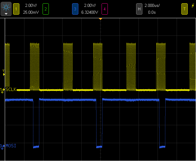
Here are the SPI signals for the Arduino Uno. Even though the SPI port uses an 8 MHz clock, less than half of the available bus time is actually used, due to significant software overhead.
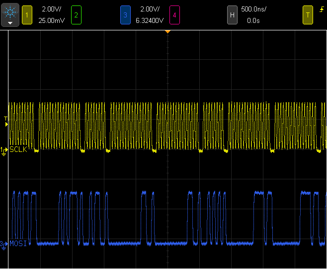
On Teensy 3.1, using a Freescale Kinetis K20, the SPI port has a 4 word FIFO. In most cases, 4 words is enough buffering to allow for the software overhead to compute more data to occur while previously written words are still transmitting.
As you can see in these waveforms, only a small gap is present between each word, limited only by the SPI port's timing. The SPI bus is nearly fully utilized, and of course the clock speed is higher (this screenshot is on a 4X faster time scale).
Actually using the SPI FIFO is a task more easily said than actually done. Several approaches were attempted throughout the development of these display optimizations.
Often when writing to hardware registers, a status bit or flag is read to check if the hardware is ready to receive data, and then then the actual data is written. However, that approach adds significant overhead when the hardware is ready, with the FIFO empty and the SPI bus idle.
A "write first, ask questions later" technique used in this display optimization always leaves at least 1 word of space available in the FIFO, which allows new data to always be written as quickly as possible. Then the FIFO is checked for full status and the code waits until at least 1 word is free.
        void writecommand_cont(uint8_t c) __attribute__((always_inline)) {
                // write first
                SPI0.PUSHR = c | (pcs_command << 16) | SPI_PUSHR_CTAS(0) | SPI_PUSHR_CONT;
                // ask questions later
                waitFifoNotFull();
        }
Using only 3 of the 4 words in the FIFO turns out to be a good trade-off, because it always slightly accelerates the commonly occuring case of a new drawing operation writing its first data to the empty FIFO. 3 words of buffering is usually enough to sustain maximum speed data flow.
A challange to use the SPI FIFO for this application, writing as rapidly as possible to MOSI while disregard all incoming data from MISO, is properly balancing read with writes, so extra data isn't left in the receive FIFO. I must confess, it took a few iteration on this latest, most optimized code to get it right. It's quite a bit more difficult that the simple but slow approach where you always write and then read a single byte.
16 Bit SPI Transfers
The SPI port requires a small idle time between words, even when another word is waiting in the FIFO. Words up to 16 bits are supported. When 8 bytes need to be sent, they can be combined into a 16 bit word to avoid the idle time.
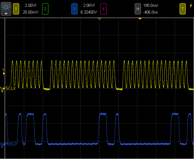
In this screenshot, 5 bytes are transmitted, but only 3 SPI idle times are needed because 4 of them are send using two 16 bit writes.
Much of the display data is 16 bits, such as X and Y coordinates and 5/6/5 color values. The 16 bit words occupy only a single entry in the SPI FIFO, so 16 bit writes also entend the time allowed for software to generate more data without the SPI bus going idle.
Hardware Control of Register Address & Chip Select
On 8 bit AVR processors, the chip select signal needs to be created by manipulating a GPIO pin. For example, the AVR code running on Arduino Uno in the video demo uses this:
      void Adafruit_ILI9341::writecommand(uint8_t c) {
        *dcport &=  ~dcpinmask;
        *csport &= ~cspinmask;
        spiwrite(c);
        *csport |= cspinmask;
      }
These extra writes to GPIO registers add overhead. They also require waiting for all 8 bits to full transmit, which greatly increases the difficulty of attempting to do any work while the SPI port is sending a byte. For complex libraries, like color graphical displays, structured programming and maintainable code usually a preferred over "spagetthi code" which might try to perform different tasks during the very short time needed to transmit 1 byte.
Fortunately, Teensy 3.1's SPI port can control up to 5 "chip select" lines. Two of them are used to control the chip select and data/command address line. The result is virtually zero extra overhead to manipulate these 2 pins.
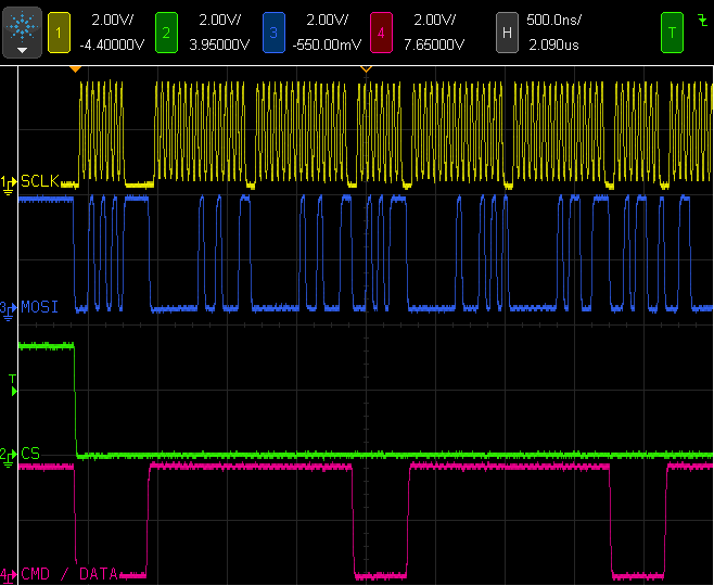
Each word in the SPI FIFO also has 5 bits for the 5 possible signals. This allows the display software to write commands and data into the FIFO, without waiting. At the SPI port uses the FIFO contents, it automatically controls both the chip select and the data/command address line. As you can see in this screenshot, in most cases command and data are transmitted to the display with only the minimum SPI idle time between each word.
However, controlling these signals does come with a cost in software complexity. Each write to the SPI port must also have a bit that tells the SPI peripheral whether to continue asserting the signals, or to de-assert them when the write is completed. This means the last write in a group must be done differently, requiring loops to be restructured so the last iteration calls the non-continue SPI write.
Display Window Addressing
Other optimizations have been added to the code, which might help on 8 bit AVR processors, but are dramatically more effective with the faster 32 bit ARM processor and FIFO-based SPI hardware.
For example, there is the simple diagonal line drawing code.
        for (; x0<=x1; x0++) {
          if (steep) {
            drawPixel(y0, x0, color);
          } else {
            drawPixel(x0, y0, color);
          }
          err -= dy;
          if (err < 0) {
            y0 += ystep;
            err += dx;
          }
        }
The drawPixel() function requires 11 bytes of SPI communication to set up the ILI9341 address window, then 2 bytes to actually write the color to the pixel.
This optimized version combines groups of horizontally or vertically adjacent pixels into a single operation, which requires 11 bytes for the entire line, and then 2 bytes per pixel. Any line at an angle other than 45 degrees involves at least some 2+ pixel segments. Because the ARM processor is fast and can do all this 16 bit integer math in single-cycle operations, and because the SPI FIFO is capable of buffering typically 5 or 6 bytes of prior output, this extra work to avoid the 11 byte address window setup rarely results in SPI idle time.
        int16_t xbegin = x0;
        if (steep) {
                for (; x0<=x1; x0++) {
                        err -= dy;
                        if (err < 0) {
                                int16_t len = x0 - xbegin;
                                if (len) {
                                        VLine(y0, xbegin, len + 1, color);
                                } else {
                                        Pixel(y0, x0, color);
                                }
                                xbegin = x0 + 1;
                                y0 += ystep;
                                err += dx;
                        }
                }
                if (x0 > xbegin + 1) {
                        VLine(y0, xbegin, x0 - xbegin, color);
                }
Another optimization uses here is inline coding of the Pixel(), VLine() and HLine() functions. These are designed to continue form write, keeping the signals asserted and making best possible use of the FIFO, until the entire line is drawn. Use of these special inline functions in drawLine() and other functions does increase the compiled code size, typically by about 5K to 8K. On Teensy 3.1, where the flash memory is 256K, an extra 5K to 8K is usually a good trade-off for a significant speed boost. But on Arduino Uno, where only 30K of flash is available for code and nearly 20K is already used, these types of optimizations that increase code size aren't usually viewed favorably.
Future Work on Large Fonts
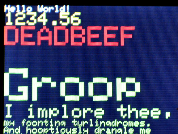
In a future version, I hope to implement arbitrary size bitmap fonts, with support for fast drawing of very large characters. The existing library only supports a single 5x7 font, with simple scaling, which looks quite blocky when scaled up to easily readable sizes on these small displays.
A large 50 to 90 pixel bitmap will look wonderful on these displays. Here is a lengthy message with my plans for supporting fast & large bitmap fonts. I'm really hoping someone with an interest in Python or other scripting languages might get involved in the project, to convert fonts into a special list-of-blocks format.
Credit Where Credit Is Due
All of this work is based on the open source libraries published by Adafruit Industries. Limor Fried and Kevin Townsend have put a tremendous amount of work into Adafruit's many display libraries. I highly recommend buying Adafruit products to support their efforts.
Peter Loveday wrote the earliest optimizations for these libraries on Teensy 3.0. My work on these optimizations continued on the path Peter started. Kurt Eckhardt was the first to port these optimizations to the ILI9341 chip. I've since redesigned much of the code.