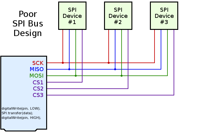
Most Arduino SPI tutorials show this simple but poor SPI bus design:
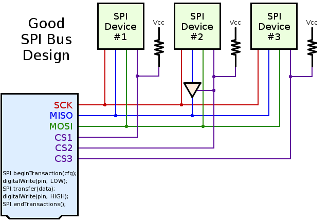
A much better SPI bus design can prevent conflicts. 3 simple improvements are needed:
Use pullup resistors on all chip select signals.
Verify tri-state behavior on MISO: use a tri-state buffer chip if necessary.
Protect bus access with SPI.beginTransaction(settings) and SPI.endTransaction().
Click "Read more" for details on these 3 steps.
Step 1: Pullup Resistors for Chip Select & Reset Signals
When multiple SPI devices are used, and especially when each is supported by its own library, pullup resistors are needed on the chip select pins.
Without a pullup resistor, the second device can "hear" and respond to the communication taking place on the first device, if that second device's chip select pin is not pulled up. This is easy to understand in hindsight, but it can be temendously confusing and frustrating to novice Arduino users who purchase shields or breakout boards without pullup resistors. Each SPI device works when used alone, but they sometimes mysteriously fail when used together, only because both devices are hearing communication meant to initialize only the first device!
A simpe workaround for devices without pullup resistor involves adding code at the beginning of setup.
    void setup() {
      pinMode(4, OUTPUT);
      digitalWrite(4, HIGH);
      pinMode(10, OUTPUT);
      digitalWrite(10, HIGH);
      delay(1);
      // now it's safe to use SD.begin(4) and Ethernet.begin()
    }
Step 2: Proper MISO Tri-State Behavior
Most SPI chips will tri-state (effectively disconnect) their MISO pin when their chip select signal is high (inactive).
However, some chips do not have proper MISO tri-state behavior. Fortunately, checking MISO tri-state is easy, especially when prototyping on a breadboard. Just connect two 10K resistors to the MISO line, like this:
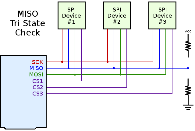
When all SPI chips are disabled, the MISO signal should "float" to approximately half the Vcc voltage. If any device is still driving the MISO line, you'll see a logic high (usually close to 3.3V or 5.0V) or logic low (close to zero volts). This test is so easy, it should always be performed by designers of Arduino compatible products.
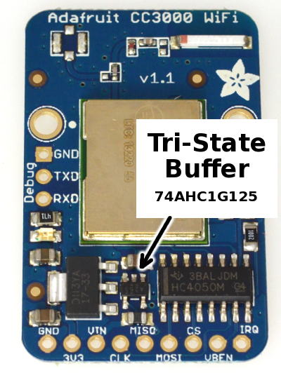
Arduino shields and breakout boards with poorly-behaved chips should always include a tri-state buffer. Adafruit's CC3000 breakout board is a good example:
Step 3: USB SPI Transactions in Software
Newer versions of Arduino's SPI library support transactions. Transactions give you 2 benefits:
- Your SPI settings are used, even if other devices use different settings
- Your device gains exclusive use of the SPI bus. Others will not disturb you.
These improvements solve software conflicts, allowing multiple SPI devices to properly share the SPI bus.
A typical use of transactions looks like this:
    SPI.beginTransaction(SPISettings(14000000, MSBFIRST, SPI_MODE0));
    digitalWrite(chipSelectPin, LOW);
    SPI.transfer(mybyte1);
    SPI.transfer(mybyte2);
    digitalWrite(chipSelectPin, HIGH);
    SPI.endTransaction();
SPI.beginTransaction() takes a special SPISettings variable, which give the maximum clock speed, the data order, and clock polarity mode. The speed is give as an ordinary number, expressing the maximum clock speed that device can use. The SPI library will automatically select the fastest clock available which is equal or less than your number. This allows your code to always use the best speed, even on board with different clock speeds.
If your code will ever call SPI library functions from within an interrupt (eg, from attachInterrupt), you must call SPI.usingInterrupt(). For example:
    SPI.begin();
    SPI.usingInterrupt(digitalPinToInterrupt(mypin));
    attachInterrupt(digitalPinToInterrupt(mypin), myFunction, LOW);
If you are developing a library that must be compatible with older versions of Arduino, which lack these SPI transaction functions, you can use SPI_HAS_TRANSACTION to check for the new version. For example:
    #ifdef SPI_HAS_TRANSACTION
    SPI.beginTransaction(SPISettings(2000000, LSBFIRST, SPI_MODE1));
    #endif
Please Share and Use This Information
Today many SPI-based products for Arduino do not work well together. My hope is this information can help all makers of Arduino compatible devices to achieve much better compatibility.
Long-term, sharing of knowledge is needed. Please share this information and ask makers of SPI devices and libraries to consider these suggestions.
This article may be shared and copied under the terms of the Creative Commons Attribution 4.0 International License. Please, copy & share! :-)
