Missing Links.
One of the joys of the Arduino Cult Induction Sessions is that mistakes and omissions are generally caught on the spot and there is no lag between the steps we forgot to include an the instructions and the person who's board isn't working.
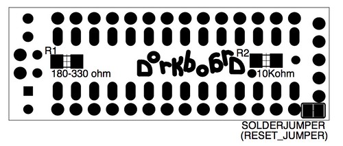
One of those steps is the Reset Jumper on the Dorkboard. The jumper is a compromise reached between myself and Brian Riley of Wuflden and Paul Badger of Modern Devices. The programmers that they are working on and the next generation of freeduino boards will have a standard pinout that the dorkboard complies with. In addition they are using the .1uf auto reset capacitor on their boards. In order to maintain compatibility with their boards and programmers I added pads for either a jumper or a small surface mount capacitor between the programming header.
If you are using a dorkbotpdx programmer you need to solder this jumper for the programmer to work.
It seems that I also failed to upload a schematic for the final revision of the dorkboard.
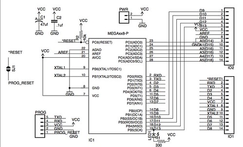
(click to view a larger sized image)
I still have not put together a complete set of instructions for building the Dorkboard outside of the induction workshops. Breedx however has started one at
/dorkboard_assembly_tutorial.
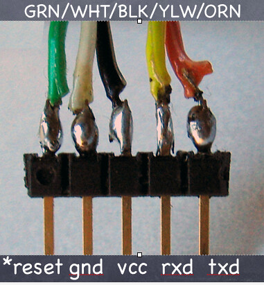
I did, however, manage to add an updated cable diagram to the
cables page.
Moments of Truth.
If you didn't make it through an induction or decided to go it alone: here is a brief description of what should happen once you have your dorkboard put together.
On your cable if you are looking at the bottom of the benito board the wires will be (from bottom to top) nc,nc,RXD,VCC,nc,TXD,RESET,GND,nc, and nc (where nc is "not connected").
Power it up.
Plugging your programmer into the usb port and hooking up the power and the ground wires (to the center post and the pin down from it on the programming header) should give you some results on a board whos processor has the dorkbotpdx adaboot lable. These processors were programmed twice: once with the adaboot boot loader, and once with a test program called blink. When you apply power to the board the led should blink erratically to tell you that its in the bootloader and then steadily.
If you are running windows windows will ask you for a driver for the device. Copy the text from
/blog/feurig/arduino_cult_induction_rev3_followup into a file called benito7g.inf and select that file. That file tells windows to use its built in drivers.
Why it cant figure that out on its own is beyond me.
Download the software.
Download the software from
http://www.arduino.cc/en/Main/Software and open the arduino application. In the tools menu select the new serial port and under board select the "Arduino Decimilia".
(If linux doesnt show the serial port check out this thread.) Then, under File->SketchBook->Examples->Digital select the blink program. This is the program that your Dorkboard should be running.
Upload your program.
Once the reset is wired (including the reset jumper) pressing the "upload to io board" button on on the bar above the code will cause the led to blink sporadically to indicate that it is going entering the bootloader. Then, if the serial lines (txd and rxd) are loaded correctly, there should be blinking lights all around followed by a message at the bottom indicating the size of the program that was just loaded.